Expanding Applications in Dry Triboelectric Separation of Minerals

Expanding Applications in Dry Triboelectric
Separation of Minerals
James D. Bittner, Kyle P. Flynn, and Frank J. Hrach
ST Equipment & Technology LLC, Needham Massachusetts 02494 USA
Tel: +1‐781‐972‐2300, email: jbittner@titanamerica.com
ABSTRACT
ST Equipment & Technology, LLC (STET) has developed a processing system based on triboelectrostatic belt separation that provides the mineral processing industry a means to beneficiate fine materials with an entirely dry technology. In contrast to other electrostatic separation processes that are typically limited to particles greater than 75μm in size, the triboelectric belt separator is ideally suited for separation of very fine (<1μm) to moderately coarse (300μm) particles with very high throughput. The high efficiency multi‐stage separation through internal charging/recharging and recycle results in far superior separations that can be achieved with a conventional single‐stage free‐ fall triboelectrostatic separator. The triboelectric belt separator technology has been used to separate a wide range of materials including mixtures of glassy aluminosilicates/carbon, calcite/quartz, talc/magnesite, and barite/quartz. An economic comparison of using the triboelectrostatic belt separation versus conventional flotation for barite / quartz separation illustrates the advantages of dry processing for minerals.
Keywords: minerals, dry separation, barite, triboelectrostatic charging, belt separator, fly ash
INTRODUCTION
The lack of access to fresh water is becoming a major factor affecting the feasibility of mining projects around the world. According to Hubert Fleming, former global director for Hatch Water, “Of all the mining projects in the world that have either been stopped or slowed down over the past year, it has been, in almost 100% of the cases, a result of water, either directly or indirectly” Blin (2013). Dry mineral processing methods offer a solution to this looming problem.
Wet separation methods such as froth flotation require the addition of chemical reagents that must be handled safely and disposed of in an environmentally responsible manner. Inevitably it is not possible to operate with 100% water recycle, requiring disposal of at least of portion of the process water, likely containing trace amounts of chemical reagents.
Dry methods such as electrostatic separation will eliminate the need for fresh water, and offer the potential to reduce costs. One of the most promising new developments in dry mineral separations is the triboelectrostatic belt separator. This technology has extended the particle size range to finer particles than conventional electrostatic separation technologies, into the range where only flotation has been successful in the past.
1
TRIBOELECTROSTATIC BELT SEPARATION
The triboelectrostatic belt separator utilizes electrical charge differences between materials produced by surface contact or triboelectric charging. When two materials are in contact, material with a higher affinity for electrons gains electrons and thus charges negative, while material with lower electron affinity charges positive. This contact exchange of charge is universally observed for all materials, at times causing electrostatic nuisances that are a problem in some industries. Electron affinity is dependent on the chemical composition of the particle surface and will result in substantial differential charging of materials in a mixture of discrete particles of different composition.
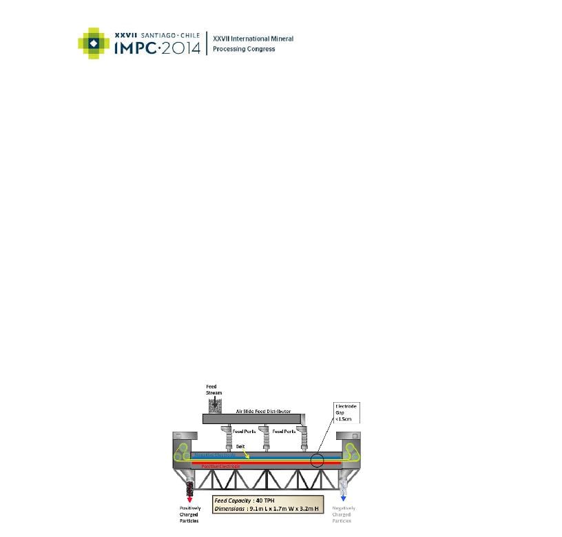
In the triboelectrostatic belt separator (Figures 1 and 2), material is fed into the thin gap 0.9 – 1.5 cm (0.35 ‐0.6 in.) between two parallel planar electrodes. The particles are triboelectrically charged by interparticle contact. For example, in the case of coal combustion fly ash, a mixture of carbon particles and mineral particles, the positively charged carbon and the negatively charged mineral are attracted to opposite electrodes. The particles are then swept up by a continuous moving open‐mesh belt and conveyed in opposite directions. The belt moves the particles adjacent to each electrode toward opposite ends of the separator. The electric field need only move the particles a tiny fraction of a centimeter to move a particle from a left‐moving to a right‐moving stream. The counter current flow of the separating particles and continual triboelectric charging by carbon‐mineral collisions provides for a multistage separation and results in excellent purity and recovery in a single‐pass unit. The high belt speed also enables very high throughputs, up to 40 tonnes per hour on a single separator. By controlling various process parameters, such as belt speed, feed point, electrode gap and feed rate, the device produces low carbon fly ash at carbon contents of 2 % ± 0.5% from feed fly ashes ranging in carbon from 4% to over 30%.
Figure 1. Schematic of triboelectric belt separator
The separator design is relatively simple. The belt and associated rollers are the only moving parts. The electrodes are stationary and composed of an appropriately durable material. The belt is made of plastic material. The separator electrode length is approximately 6 meters (20 ft.) and the width 1.25 meters (4 ft.) for full size commercial units. The power consumption is about 1 kilowatt‐hour per tonne of material processed with most of the power consumed by two motors driving the belt.
2
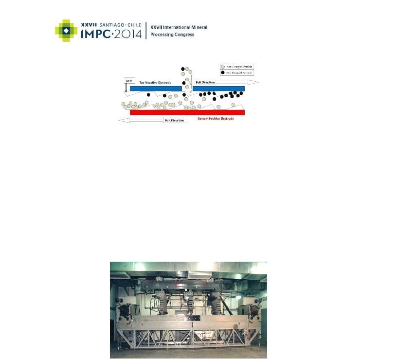
Figure 2. Detail of separation zone
The process is entirely dry, requires no additional materials and produces no waste water or air emissions. In the case of carbon from fly ash separations, the recovered materials consist of fly ash reduced in carbon content to levels suitable for use as a pozzolanic admixture in concrete, and a high carbon fraction which can be burned at the electricity generating plant. Utilization of both product streams provides a 100% solution to fly ash disposal problems.
The triboelectrostatic belt separator is relatively compact. A machine designed to process 40 tonnes per hour is approximately 9.1 meters (30 ft) long, 1.7 meters (5.5 ft.) wide and 3.2 meters (10.5 ft.) high. The required balance of plant consists of systems to convey dry material to and from the separator. The compactness of the system allows for flexibility in installation designs.
Figure 3. Commercial triboelectrostatic belt separator
Comparison to other electrostatic separation processes
The triboelectrostatic belt separation technology greatly expands the range of materials that can be beneficiated by electrostatic processes. The most commonly used electrostatic processes rely on differences in the electrical conductivity of the materials to be separated. In these processes, the material must contact a grounded drum or plate typically after the material particles are negatively charged by an ionizing corona discharge. Conductive materials will lose their charge quickly and be thrown from the drum. The non‐conductive material continues to be attracted to the drum since the
3
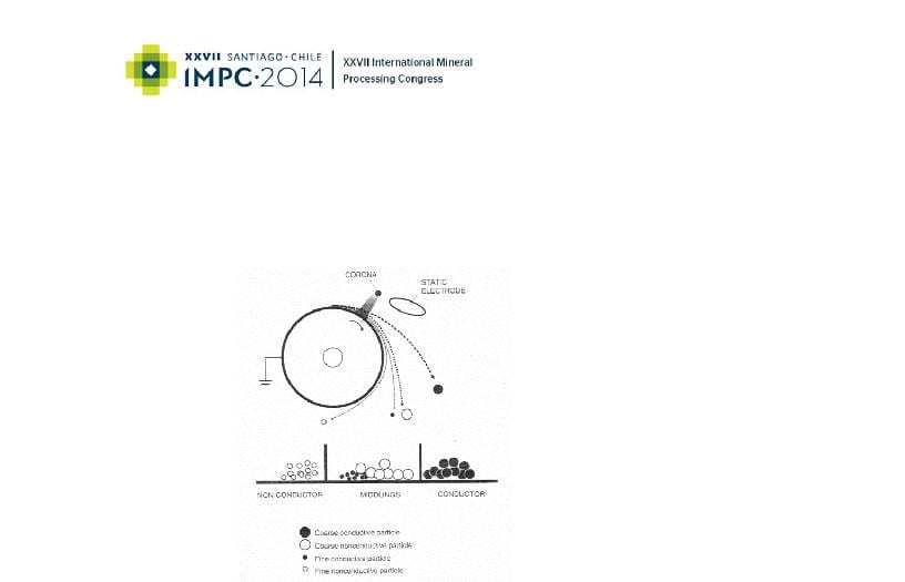
charge will dissipate more slowly and will fall or be brushed from the drum after separation from the conducting material. These processes are limited in capacity due to the required contact of every particle to the drum or plate. The effectiveness of these contact charging processes are also limited to particles of about 100 μm or greater in size due to both the need to contact the grounded plate and the required particle flow dynamics. Particles of different sizes will also have different flow dynamics due to inertial effects and will result in degraded separation. The following diagram (Figure 4) illustrates the fundamental features of this type of separator.
Figure 4. Drum electrostatic separator “Elder (2003)”
Triboelectrostatic separations are not limited to separation of conductive / non‐conductive materials but depend on the well known phenomenon of charge transfer by frictional contact of materials with dissimilar surface chemistry. This phenomenon has been used in “free fall” separation processes for decades. Such a process is illustrated in Figure 5. Components of a mixture of particles first develop different charges by contact either with a metal surface, or by particle to particle contact in a fluidized bed feeding device. As the particles fall through the electric field in the electrode zone, each particle’s trajectory is deflected toward the electrode of opposite charge. After a certain distance, collection bins are employed to separate the streams. Typical installations require multiple separator stages with recycle of a middling fraction. Some devices use a steady stream of gas to assist the conveying of the particles through the electrode zone.
4
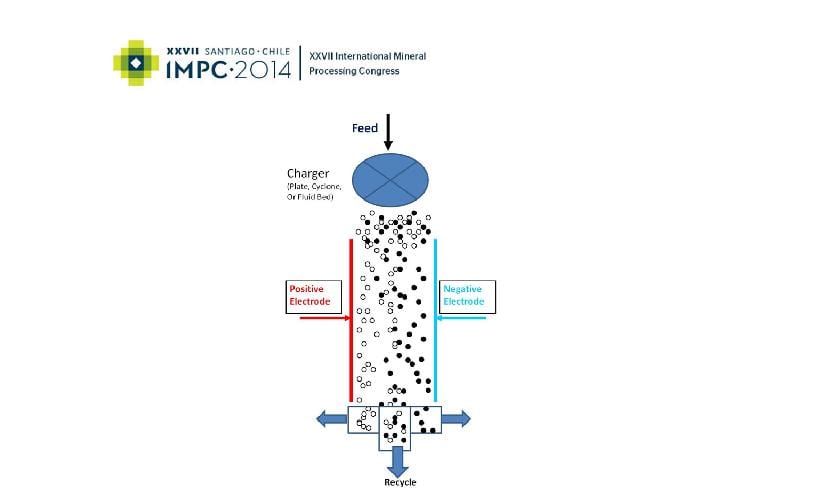
Figure 5. “Free fall” triboelectrostatic separator
This type of free fall separator also has limitations in the particle size of the material that can be processed. The flow within the electrode zone must be controlled to minimize turbulence to avoid “smearing” of the separation. The trajectory of fine particles are more effected by turbulence since the aerodynamic drag forces on fine particles are much larger than the gravitational and electrostatic forces. The very fine particles will also tend to collect on the electrode surfaces and must be removed by some method. Particles of less than 75 μm cannot be effectively separated.
Another limitation is that the particle loading within the electrode zone must be low to prevent space charge effects, which limit the processing rate. Passing material through the electrode zone inherently results in a single‐stage separation, since there is no possibility for re‐charging of particles. Therefore, multi‐stage systems are required for improving the degree of separation including re‐charging of the material by subsequent contact with a charging device. The resulting equipment volume and complexity increases accordingly.
In contrast to the other available electrostatic separation processes, the triboelectrostatic belt separator is ideally suited for separation of very fine (<1 μm) to moderately coarse (300μm) materials with very high throughputs. The triboelectric particle charging is effective for a wide range of materials and only requires particle – particle contact. The small gap, high electric field, counter current flow, vigorous particle‐particle agitation and self‐cleaning action of the belt on the electrodes are the critical features of the separator. The high efficiency multi‐stage separation through charging / recharging and internal recycle results in far superior separations and is effective on fine materials that cannot be separated at all by the conventional techniques.
5
APPLICATIONS OF TRIBOELECTROSTATIC BELT SEPARATION
Fly Ash
The triboelectrostatic belt separation technology was first applied industrially to the processing of coal combustion fly ash in 1995. For the fly ash application, the technology has been effective in separating carbon particles from the incomplete combustion of coal, from the glassy aluminosilicate mineral particles in the fly ash. The technology has been instrumental in enabling recycle of the mineral‐rich flyash as a cement replacement in concrete production. Since 1995, 19 triboelectrostatic belt separators have been operating in the USA, Canada, UK, and Poland, processing over 1,000,000 tonnes of fly ash annually. The technology is now also in Asia with the first separator installed in South Korea this year. The industrial history of fly ash separation is listed in Table 1.
|
Table 1 |
Industrial Application of Triboelectrostatic belt separation for fly ash |
|
||
|
Utility / power station |
Location |
Start of |
Facility |
|
|
|
|
|
industrial |
details |
|
|
|
|
operations |
|
|
Duke Energy – Roxboro Station |
North Carolina USA |
1997 |
2 Separators |
|
|
Raven Power‐ Brandon Shores |
Maryland USA |
1999 |
2 Separators |
|
|
Scottish Power‐ Longannet Station |
Scotland UK |
2002 |
1 Separator |
|
|
Jacksonville Electric‐St. John’s |
Florida USA |
2003 |
2 Separators |
|
|
River Power Park |
|
|
|
|
|
South Mississippi Electric Power ‐ |
Mississippi USA |
2005 |
1 Separator |
|
|
R.D. Morrow |
|
|
|
|
|
New Brunswick Power‐Belledune |
New Brunswick Canada |
2005 |
1 Separator |
|
|
RWE npower‐Didcot Station |
England UK |
2005 |
1 Separator |
|
|
PPL‐Brunner Island Station |
Pennsylvania USA |
2006 |
2 Separators |
|
|
Tampa Electric‐Big Bend Station |
Florida USA |
2008 |
3 Separators, |
|
|
|
|
|
|
double pass |
|
RWE npower‐Aberthaw Station |
Wales UK |
2008 |
1 Separator |
|
|
EDF Energy‐West Burton Station |
England UK |
2008 |
1 Separator |
|
|
ZGP (Lafarge Cement Poland / |
Poland |
2010 |
1 Separator |
|
|
Ciech Janikosoda JV) |
|
|
|
|
|
Korea Southeast Power‐ Yong |
South Korea |
2014 |
1 Separator |
|
|
Heung |
|
|
|
|
Mineral Applications
Electrostatic separations have been extensively used for beneficiation for a large range of minerals “Manouchehri‐Part 1 (2000)”. While most application utilize differences in electrical conductivity of materials with the corona‐drum type separators, triboelectric charging behavior with free‐fall separators is also used at industrial scales “Manouchehri‐Part 2 (2000)”. A sample of applications of triboelectrostatic processing reported in the literature is listed in Table 2. While this is not an exhaustive listing of applications, this table illustrates the potential range of applications for electrostatic processing of minerals.
Table 2. Reported triboelectrostatic separation of minerals
|
Mineral Separation |
Reference |
Triboelectrostatic belt |
|
|
|
separation Experience |
|
|
|
|
|
Potassium Ore – Halite |
4,5,6,7 |
YES |
|
Talc – Magnesite |
8,9,10 |
YES |
|
Limestone – quartz |
8,10 |
YES |
|
Brucite – quartz |
8 |
YES |
|
Iron oxide – silica |
3,7,8,11 |
YES |
|
Phosphate – calcite – silica |
8,12,13 |
|
|
Mica ‐ Feldspar – quartz |
3,14 |
|
|
Wollastonite – quartz |
14 |
YES |
|
Boron minerals |
10,16 |
YES |
|
Barites – Silicates |
9 |
YES |
|
Zircon – Rutile |
2,3,7,8,15 |
|
|
Zircon‐Kyanite |
|
YES |
|
Magnesite‐Quartz |
|
YES |
|
Silver and gold slags |
4 |
|
|
Carbon – Aluminosilicates |
8 |
YES |
|
Beryl – quartz |
9 |
|
|
Fluorite – silica |
17 |
YES |
|
Fluorite – Barite ‐ Calcite |
4,5,6,7 |
|
|
|
|
|
Extensive pilot plant and field testing of many challenging material separations in the minerals industry have been conducted using the triboelectrostatic belt separator. Examples of separation results are shown in Table 3.
7
Table 3. Examples, mineral separations using triboelectrostatic belt separation
|
Mineral |
Calcium Carbonate |
Talc |
|
|
|
|
|
|
|
Separated materials |
CaCO3 – SiO2 |
Talc / Magnesite |
|
|
Feed composition |
90.5% CaCO3 |
/ 9.5% SiO2 |
58% talc / 42% Magnesite |
|
Product composition |
99.1% CaCO3 |
/ 0.9% SiO2 |
95% talc / 5% Magnesite |
|
Mass yield product |
82% |
46% |
|
|
Mineral recovery |
89% CaCO3 |
Recovery |
77% Talc Recovery |
|
|
|
|
|
Use of the triboelectrostatic belt separator has been demonstrated to effectively beneficiate many mineral mixtures. Since the separator can process materials with particle sizes from about 300 μm to less than 1 μm, and the triboelectrostatic separation is effective for both insulating and conductive materials, the technology greatly extends the range of applicable material over conventional electrostatic separators. Since the triboelectrostatic process is entirely dry, use of it eliminates the need for material drying and liquid waste handling from flotation processes.
COST OF TRIBOELECTROSTATIC BELT SEPARATION
Comparison to Conventional Flotation for Barite
A comparative cost study was commissioned by STET and conducted by Soutex Inc. Soutex is a Quebec Canada based engineering company with extensive experience in both wet flotation and electrostatic separation process evaluation and design. The study compared the capital and operating costs of triboelectrostatic belt separation process to conventional froth flotation for the beneficiation of a low‐grade barite ore. Both technologies upgrade the barite by removal of low density solids, mainly quartz, to produce an American Petroleum Institute (API) drilling grade barite with SG greater than 4.2 g/ml. Flotation results were based on pilot plant studies conducted by the Indian National Mettalurgical Laboratory “NML (2004)”. Triboelectrostatic belt separation results were based on pilot plant studies using similar feed ores. The comparative economic study included flowsheet development, material and energy balances, major equipment sizing and quotation for both flotation and triboelectrostatic belt separation processes. The basis for both flowsheets is the same, processing 200,000 t/y of barite feed with SG 3.78 to produce 148,000 t/y of drilling grade barite product with SG 4.21 g/ml. The flotation process estimate did not include any costs for process water, or water treatment.
Flowsheets were generated by Soutex for the barite flotation process (Figure 6), and triboelectrostatic belt separation process (Figure 7).
8
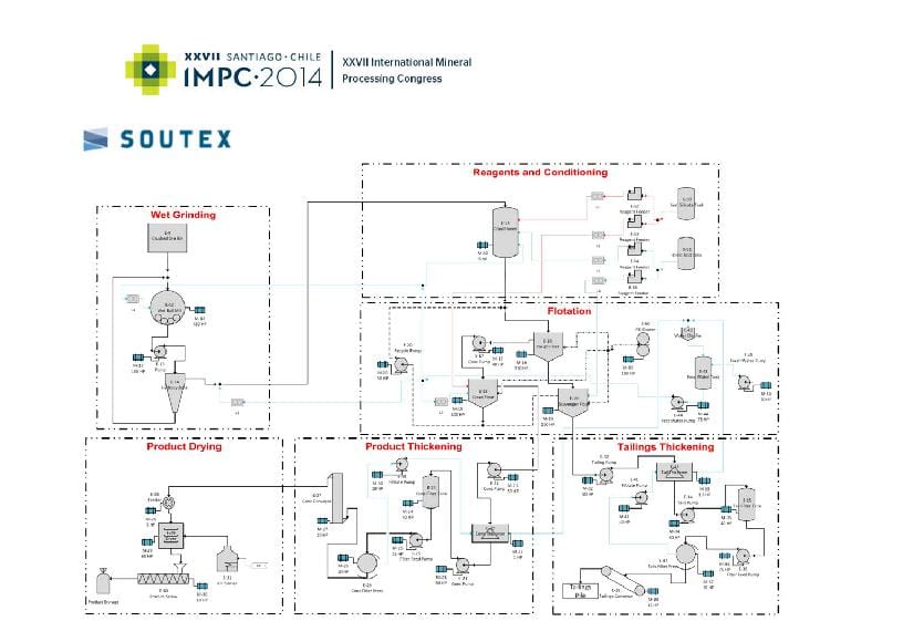
Figure 6 Barite flotation process flowsheet
9
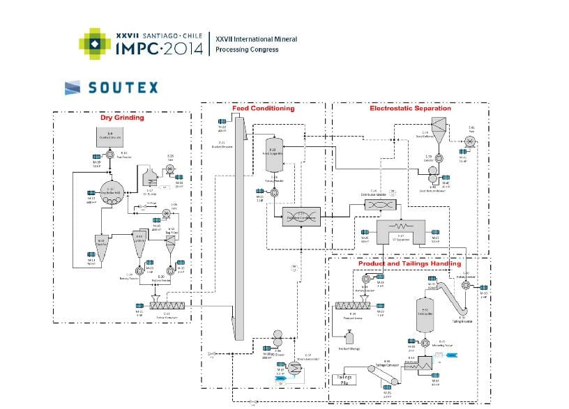
Figure 7 Barite triboelectrostatic belt separation process flowsheet
Theses flowsheets do not include a raw ore crushing system, which is common to both technologies. Feed grinding for the flotation case is accomplished using a wet pulp ball mill with cyclone classifier. Feed grinding for the triboelectrostatic belt separation case is accomplished using a dry, vertical roller mill with integral dynamic classifier.
The triboelectrostatic belt separation flowsheet is simpler than flotation. Triboelectostatic belt separation is achieved in a single stage without the addition of any chemical reagents, compared to three‐stage flotation with oleic acid used as a collector for barite and sodium silicate as a depressant for the silica gangue. A flocculant is also added as a reagent for thickening in the barite flotation case. No dewatering and drying equipment is required for triboelectrostatic belt separation, compared to thickeners, filter presses, and rotary dryers required for the barite flotation process.
10
Capital and Operating Costs
A detailed capital and operating cost estimate was performed by Soutex for both technologies using equipment quotations and the factored cost method. The operating costs were estimated to include operating labor, maintenance, energy (electrical and fuel), and consumables (e.g, chemical reagent costs for flotation). The input costs were based on typical values for a hypothetical plant located near Battle Mountain, Nevada USA. The total cost of ownership over ten years was calculated from the capital and operating cost by assuming an 8% discount rate. The results of cost comparison are present as relative percentages in Table 4
Table 4. Cost Comparison for Barite Processing
|
|
Wet Beneficiation |
Dry Beneficiation |
|
Technology |
Froth flotation |
Triboelectrostatic belt separation |
|
|
|
|
|
Purchased Major Equipment |
100% |
94.5% |
|
Total CAPEX |
100% |
63.2% |
|
Annual OPEX |
100% |
75.8% |
|
Unitary OPEX ($/ton conc.) |
100% |
75.8% |
|
Total Cost of Ownership |
100% |
70.0% |
|
|
|
|
The total purchase cost of capital equipment for the triboelectrostatic belt separation process is slightly less than for flotation. However when the total capital expenditure is calculated to include equipment installation, piping and electrical costs, and process building costs, the difference is large. The total capital cost for the triboelectrostatic belt separation process is 63.2% of the cost of the flotation process. The significantly lower cost for the dry process results from the simplier flowsheet. The operating costs for the triboelectrostatic belt separation process is 75.5% of the flotation process due to mainly lower operating staff requirements and lower energy consumption.
The total cost of ownership of the triboelectrostatic belt separation process is significantly less than for flotation. The study author, Soutex Inc., concluded that the triboelectrostatic belt separation process offers obvious advantages in CAPEX, OPEX, and operational simplicity.
11
CONCLUSION
The triboelectrostatic belt separator provides the mineral processing industry a means to beneficiate fine materials with an entirely dry technology. The environmentally friendly process can eliminate wet processing and required drying of the final material. The process requires little, if any, pre‐treatment of the material other than grinding and operates at high capacity – up to 40 tonnes per hour by a compact machine. Energy consumption is low, less than 2 kWh/tonne of material processed. Since the only potential emission of the process is dust, permitting is relatively easy.
A cost study comparing the triboelectrostatic belt separation process to conventional froth flotation for barite was completed by Soutex Inc. The study shows that the total capital cost for for the dry triboelectrostatic belt separation process is 63.2% of the flotation process. The total operating cost for tribo electrostatic belt separation is 75.8% of operating cost for flotation. The study’s author concludes that the dry, triboelectrostatic belt separation process offers obvious advantages in CAPEX, OPEX, and operational simplicity.
12
REFERENCES
1.Blin, P & Dion‐Ortega, A (2013) High and Dry, CIM Magazine, vol. 8, no. 4, pp. 48‐51.
2.Elder, J. & Yan, E (2003) eForce.‐ Newest generation of electrostatic separator for the minerals sands industry, Heavy Minerals Conference, Johannesburg, South African Institute of Mining and Metallurgy.
3.Manouchehri, H, Hanumantha Roa,K, & Foressberg, K (2000), Review of Electrical Separation Methods, Part 1: Fundamental aspects, Minerals & Metallurgical Processing, vol 17, no. 1 pp 23 – 36.
4.Manouchehri, H, Hanumantha Roa, K, & Foressberg, K (2000), Review of Electrical Separation Methods, Part 2: Practical Considerations, Minerals & Metallurgical Processing, vol 17, no. 1 pp 139‐ 166.
5.Searls, J (1985) Potash, Chapter in Mineral Facts and Problems: 1985 Edition, United States Bureau of Mines, Washington DC.
6.Berthon, R & Bichara, M, (1975) Electrostatic Separation of Potash Ores, United States Patent # 3,885,673.
7.Brands, L, Beier, P, & Stahl, I (2005) Electrostatic Separation, Wiley‐VCH verlag, GmbH & Co.
8.Fraas, F (1962) Electrostatic separation of Granular Materials, US Bureau of Mines, Bulletin 603.
9.Fraas, F (1964), Pretreatment of minerals for electrostatic separation, US Patent 3,137,648.
10.Lindley, K & Rowson, N (1997) Feed preparation factors affecting the efficiency of electrostatic separation, Magnetic and Electrical Separation, vol 8 pp 161‐173.
11.Inculet, I (1984) Electrostatic Mineral Separation, Electrostatics and Electrostatic Applications Series, Research Studies Press, Ltd, John Wiley & Sons, Inc.
12.Feasby, D (1966) Free‐Fall Electrostatic Separation of Phosphate and Calcite Particles, Minerals Research Laboratory, Labs Nos. 1869, 1890, 1985, 3021, and 3038, book 212, Progress Report.
13.Stencel, J & Jiang, X (2003) Pneumatic Transport, Triboelectric Beneficiation for the Florida Phosphate Industry, Florida Institute of Phosphate Research, Publication No. 02‐149‐201, December.
14.Manouchehri, H, Hanumantha R, & Foressberg, K (2002), Triboelectric Charge, Electrophysical properties and Electrical Beneficiation Potential of Chemically Treated Feldspar, Quartz, and Wollastonite, Magnetic and Electrical Separation, vol 11, no 1‐2 pp 9‐32.
15.Venter, J, Vermaak, M, & Bruwer, J (2007) Influence of surface effects on the electrostatic separation of zircon and rutile, The 6th International Heavy Minerals Conference, The Southern African Institute of Mining and Metallurgy.
16.Celik, M and Yasar, E (1995) Effects of Temperature and Impurities on Electrostatic Separation of Boron Materials, Minerals Engineering, vol. 8, no. 7, pp. 829‐833.
17.Fraas, F (1947) Notes on Drying for Electrostatic Separation of Particles, AIME Tec. Pub 2257, November.
18.NML (2004) Beneficiation of low grade barite (pilot plant results), Final Report, National Metallurgical Laboratory, Jamshedpur India, 831 007
13


